Half way december i switched to another team at my current employer, and got my hands dirty with Cloud director, NSX-T and AVI. As this was my first real hands-on with VMware Cloud Director.
I was given the task to investigate some scenarios in which a tenant is given a second Edge Gateway, for the separation of Internet and Customer Networks traffic.
Before describing the scenarios, I’ll assume you have basic NSX-T, routing and VCD knowledge.
Current Tenant Setup
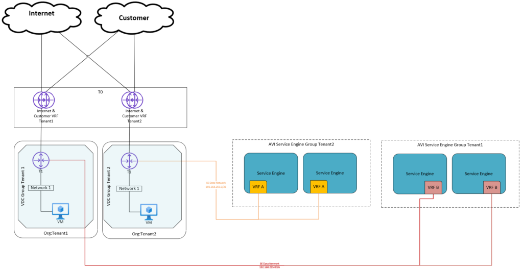
In the current setup a tenant is given:
- Cloud Director (10.3): Organization (example: Tenant1)
- Cloud Director: Org VDC
- NSX-T (3.2): VRF based tier-0 gateway for both Internet VRF and Customer VRF connected to Parent T0
- Cloud Director NSX-T: 1 Edge Gateway (T1)
- Clloud Director NSX-T: 1 VDC Group
- If Load balancing is used: dedicated AVI Service Engine Group
Because there is a 1:1 relation between the T0 and the Edge Gateway (dedicated T0), route advertisement of connected tenant networks is available.

The traffic for both the customer networks and Internet is flowing through the same Tenant Edge gateway and VRF based tier-0 gateway.
Scenario 1 – 2 Edge Gateways Connected to 1 Shared T0.
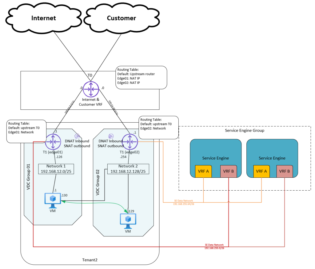
The first scenario I tested is based on a Shared T0 (in VCD) and 2 Edge Gateways (1 for Internet and 1 for Customer Networks).
Setup:
- Cloud Director: Organization (example: Tenant1)
- Cloud Director: Org VDC
- NSX-T: VRF based tier-0 gateway for both Internet VRF and Customer VRF connected to Parent T0 (parent T0 is shared between 5 Tenants)
- Cloud Director NSX-T: Set T0 to shared
- Cloud Director NSX-T: two Edge Gateway (T1) connected to the same T0 (shared)
- Cloud Director NSX-T: two VDC Groups (Data Center Groups)
- If Load balancing is used: Shared AVI Service Engine Group (dedicated as described in current setup can also be used).
The downside of a Shared T0 is that route advertising of Tenant network connected to the Edge Gateway (T1) isn’t available to the T0.
Tenant VMs can connect to the internet or customer networks by using NAT and firewall rules.
SNAT rules need to be created for outbound traffic and DNAT rules inbound traffic.
Only use private IP spaces can be used for tenant networks connected to the Edge Gateway (T1).
Also because we use two Edge Gateways in an Org VDC we need to create 2 VDC Groups (Data Center Groups), because there is a restriction of 1 Edge Gateway per VDC Group (Data Center Group), two Datacenter Groups also mean 2 Distributed Firewalls to manage.
If you need connection between a VM in VDC Group 1 and a VM in VDC Group 2, you can create a network that will be spanning across both VDC groups.
In this scenario we still have the BGPs for both Internet and Customer configured on 1 VRF based tier-0 gateway, so this is not completely dedicated. And it is giving a lot of extra effort configuring the SNAT and DNAT.
We also worked out a scenario if the tenant is using AVI. In the normal setup the tenat is given a dedicated Service Engine Group. We also discovered the option to share the Service Engine Group between the Internet and Customer Networks. This option is a valid solution as the AVI per Default configures separates the traffic based on VRF in the Service Engines.

Scenario 2 – 2 Edge GW with dedicated T0
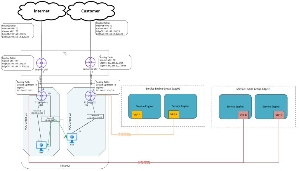
For the 2nd scenario we decoupled also the VRF Based T0 and creating again a 1:1 relation (dedicated T0) between the Edge Gateway and the VRF Based T0’s. Because of this 1:1 relationship route advertisements are available to the T0.
Setup:
- Cloud Director: Organization (example: Tenant1)
- Cloud Director: Org VDC
- NSX-T: VRF based tier-0 gateway for Internet VRF connected to Parent T0
- NSX-T: VRF based tier-0 gateway for Customer VRF connected to Parent T0
- Cloud Director NSX-T: Set T0 to be dedicated
- Cloud Director NSX-T: two Edge Gateway (T1) connected to the dedicated T0
- Cloud Director NSX-T: two VDC Groups (Data Center Groups)
- If Load balancing is used: Dedicated AVI Service Engine Group (because no design Change is needed for current model)
If you need connection between a VM in VDC Group 1 and a VM in VDC Group 2, you can created a network that will be spanning across both VDC groups.
The downside of the Scenario is that there are a lot of extra resources needed, and these resources will be billed to the tenant.

Conclusion
We still wanted a Design that met the customer requirements and also is easy to implement in the current setup. Which already in use by several tenants and was the default tenant setup when the platform was initially designed.
In Scenario 1 the Shared setup of the shared VRF based T0 doesn’t met the Customer requirements of separating Customer Networks and Internet traffic. Also the lack of the route advertisements was an issue for the Tenant.
In Scenario 2 where we separated all parts of the setup, all the Tenant requirements were met. The downside of this Scenario is that because all parts of the setup are decoupled, the resources a tenant needs using this setup are doubled. This means:
- Double Billing
- Double Resources, check the Config Maxs
- Increases operational effort
Scenario 2 is basically a copy of the current scenario, so the initial setup will cost less time, where Scenario 1 will have some design changes (shared T0, no route advertisments, SNAT/DNAT).
This design was based upon some requirements of a tenant, i tried to take in account that we also van use this for other tenants with the same requirements.
I loved investigating these scenarios, and discovering Cloud Director! Watch out for the next post about a Test Case with RBAC on Cloud Director!
Thank you for reading!
I also would like to mention the following blog article that helped me creating this post, Thanks Daniël!
https://blog.zuthof.nl/2020/06/30/cloud-director-nsx-t-inter-tenant-routing/

Pingback: Test Case – Cloud Director NSX-T Role Based Access -